Improving Data Center Cooling Efficiency & PUE
Data centers are the new backbone of the American economy
From the centralized data centers that support Fortune 500 corporations, to the local server rooms that keep our SMEs running, to the cloud computing farms hosted by Amazon, Facebook, Google, and others, data centers are the new backbone of the American economy. The explosion of stored data, e-commerce, and internet traffic has made data centers one of the fastest-growing users of electricity in the United States. As the factories of the digital age, data centers require substantial amounts of energy while also presenting major opportunities for decoupling of economic growth from environmental impact.
In 2015, US data centers consumed an estimated 71 billion kilowatt-hours of electricity, or about 2% of total consumption. This usage is equivalent to the annual output of 34 large (500-megawatt) coal-fired power plants and is enough to power all the households in New York City twice over. This consumption costs American businesses nearly $9 billion per year and results in the emission of nearly 100 million metric tons of carbon pollution. Needless-to-say, data centers offer a tremendous opportunity for cost savings and environmental benefits.
Strategies for Improved Air Flow Management and Cooling Efficiency
The single largest inefficiency in data center energy use is through over-cooling. A recent study concluded that, on average, only 60% of the cool air being pumped into data centers is effectively utilized in cooling equipment due to poor air flow management. For this reason, most cooling units are set to supply air that is up to 8° C colder than necessary to ensure that critical equipment cooling meets ASHRAE TC 9.9 recommendations. This practice results in a significant loss of efficiency.
Among the strategies for improving air flow in data centers are the following, listed in order of increasing complexity:
Blanking panels are fundamental to efficient airflow control in server racks. On the front of server racks, unused rack spaces (open areas) are covered with blanking plates so that air passes through the equipment rather than around it. Similarly, spaces between racks and between racks and adjacent partitions should be closed or eliminated. This method reduces the recirculation of hot air from server exhaust to the inlet side of the racks.
A Hot/Cold Aisle Arrangement orienting the rows of server racks so that the fronts of adjacent server racks face each other and, conversely, the backs of adjacent server racks will also face each other. This orientation creates alternating "hot aisle/cold aisle" rows minimize mixing of cold air with hot air prior to cooling equipment. Hot/Cold aisle designs are now standard and are used in more than 80% of existing facilities.
Vented tiles (diffusers) and/or grated panels are incorrectly located or sized in many data centers. Due to the complexity of airflow behavior, the correct configurations are not readily obvious and fluid dynamics studies are needed for evaluation.
Cold or hot aisle containment augments the hot aisle/cold aisle arrangement by enclosing one or the other of the aisles. The enclosed aisle then becomes a room unto itself, sealed with barriers made of metal, plastic, or plexiglass, and all but eliminating hot-cold air mixing and cold air bypass of the racks.
Baseline Air Flow Evaluation with Computational Fluid Dynamics (CFD)
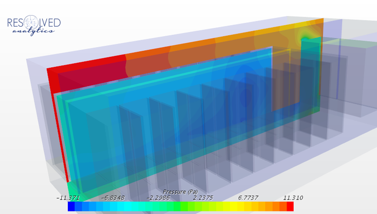
Recently, at Resolved Analytics, we were asked to demonstrate for a customer the efficiency gains that would be realized by taking these steps on an existing hot aisle-cold aisle server room arrangement through the use of Computational Fluid Dynamics (CFD) modeling. We begin with a demonstration of the inefficiency associated with the baseline hot aisle-cold aisle arrangement. For reference, the servers modeled are producing 6 kW of heat per rack with an air throughput of 0.36 kg/s and perforated tile porosity of 50%. The Cooling Room Air Conditioning (CRAC) unit is shown on the far right.
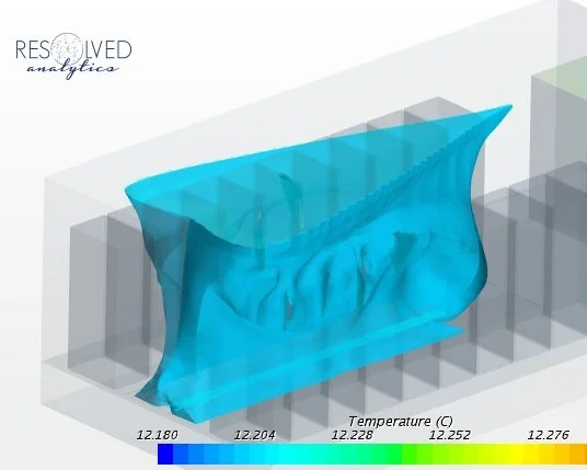
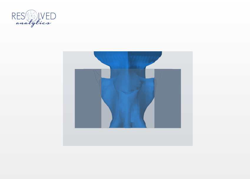
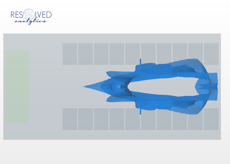
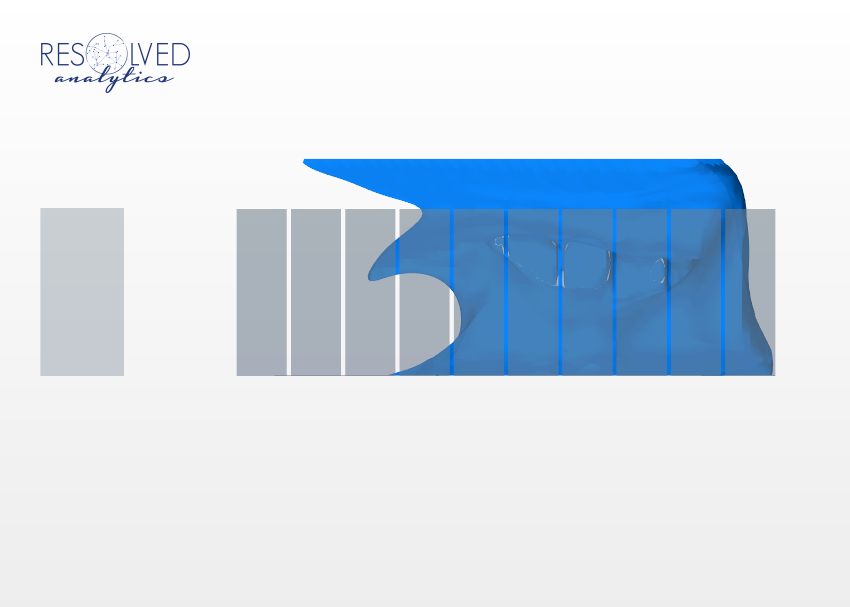
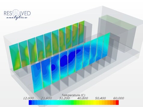
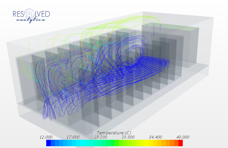
Seen in the following figures, the plume of cold air rising from the raised floor vent tiles is clearly concentrated towards servers at the rear of the room and bypasses most server inlets before reaching the ceiling and mixing with warm air recirculating from the hot air exhausts of the servers.
The result is that some servers experience inlet temperatures as hot as 34C, or 22C above the CRAC air temperatures. Likewise, servers that experience high inlet temperatures also demonstrate higher than design outlet temperatures (hot spots) that could negatively impact the CRACs ability to maintain ASHRAE standards. These data points closely resembled the customer's operational experience.
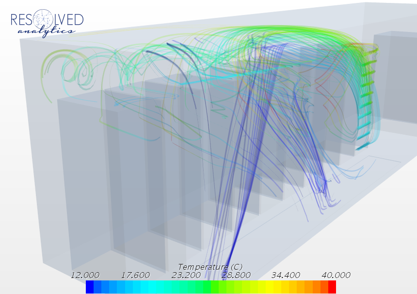
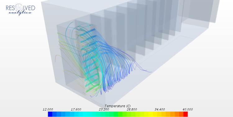
Streamline plots demonstrate that the warm exhaust air is being recirculated from the racks furthest from the CRAC and mixes with CRAC supply air before entering the intakes of servers closer to the CRAC. Likewise, exhaust air is drawn into the bottom of each rack due to an unsealed 2" space at the floor level and on the sides due to a 1" space left open between adjacent racks.
Addition of Blanking and Cold Aisle Containment
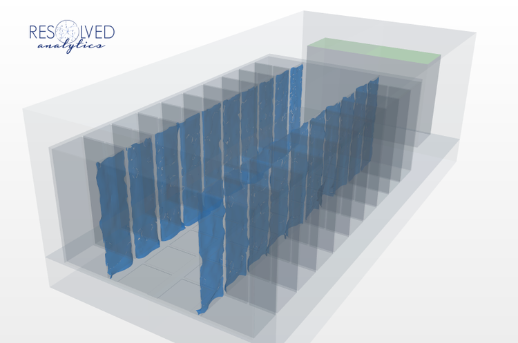
Additional simulations were performed to demonstrate the step-wise improvements associated with various modifications including adding blanking panels to close off the spaces between racks, varying the porosity of individual diffuser tiles, and varying the height of the CRAC return, which are not included here. But, we do share below the results from the CFD simulation of the cold aisle containment arrangement. The 12C isosurface plot below, analogous to that shown previously, demonstrates the ideally uniform distribution of cold air across all server rack inlets.
Conclusions
Here we have reported on the successful application of Computational Fluid Dynamics (CFD) modeling in demonstrating the cooling efficiency impacts of various data center equipment arrangement modifications. The project demonstrated that the data center operator could expect to increase CRAC temperatures by between 2 to 10C, depending upon which modifications were chosen, while also experiencing increased ASHRAE compliance. With this information in hand, the data center operator was then able to make an informed cost/benefit analysis to determine the modifications that best suited their needs.
If you have a data center air flow management concern and think CFD may be a useful tool in assessing your problem, please don't hesitate to get in touch with us and thanks for reading.