What is the CFD Workflow
Exploring Workflow in Commercial CFD Software Programs
Computational fluid dynamics (CFD) software has increasingly become an indispensable tool for engineers in various industries such as aerospace, automotive, and oil and gas. CFD software programs provide a platform to simulate fluid behavior and interact with the physical world in a virtual environment. However, working with these tools requires an understanding of the workflow that governs the simulation process from geometry to results.
The Simulation Process
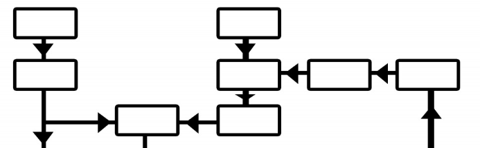
Before diving into the simulation process, it's essential to note that CFD software programs can differ significantly in structure and interface. Nevertheless, the underlying workflow is typically similar. The CFD simulation process comprises three primary stages: preprocessing, solver, and post-processing. Each stage is essential and should be approached with diligence in mind.
Preprocessing Stage
The preprocessing stage is where the user sets up the simulation environment. This stage involves defining the geometry, mesh generation, and boundary conditions. Defining the geometry involves importing the 3D model of the object or system to be simulated. Mesh generation involves dividing the geometry into small cells for numerical analysis. Boundary conditions refer to the physical conditions at the edges of the simulation environment. These conditions can include temperature, pressure, and velocity.
The preprocessing stage is crucial because it sets the foundation for the entire simulation. A poorly defined geometry or boundary conditions can lead to inaccurate results and wasted time and resources.
Solver Stage
The solver stage is where the actual simulation takes place. The CFD software solves the mathematical equations that describe the fluid flow within the simulation environment. The solver stage can be computationally intensive and may require significant resources, such as high-performance computing systems. The solver stage typically involves iterative calculations until a stable solution is achieved.
During the solver stage, it's essential to monitor the simulation's progress and ensure that the solution is stable and accurate. If the solution is unstable or inaccurate, adjustments to the preprocessing stage may be necessary.
Post-processing Stage
The post-processing stage involves analyzing and interpreting the simulation results. This stage includes visualizing the flow field, generating graphs and charts, and extracting relevant data. Visualization tools can help the user understand the flow behavior and identify potential issues. Graphs and charts can help the user compare different scenarios and make informed decisions. Extracted data can be used for further analysis or to validate the simulation results.
The post-processing stage is critical because it provides insight into the simulation results. Without proper analysis, the simulation results may be misunderstood or misinterpreted.
Conclusion
The CFD simulation process comprises three primary stages: preprocessing, solver, and post-processing. Each stage is essential and should be approached with diligence in mind. The preprocessing stage sets the foundation for the entire simulation, the solver stage involves the actual simulation, and the post-processing stage provides insight into the simulation results. By following a structured and thorough process, the user can achieve accurate and reliable results.
Geometry - The Foundation of Your CFD Model
The field of computational fluid dynamics (CFD) is a powerful tool for simulating fluid flow and heat transfer in a variety of engineering applications. The accuracy of a CFD simulation depends on many factors, including the quality of the geometry used to define the problem.
Geometry is the foundation on which the simulation process is built. It describes the physical objects, boundaries, and the domain of the simulation. In commercial CFD software programs, creating the geometry can be done using inbuilt tools or imported from third-party computer-aided design (CAD) software programs.
Creating a high-quality geometry is crucial to the success of a CFD simulation. The geometry should be clean, free from errors, and regularly checked for completeness. Any errors at this stage will propagate throughout the simulation process and produce erroneous results.
One important consideration when creating a geometry is the level of detail required. For example, in a simulation of fluid flow over an aircraft wing, the geometry must accurately capture the shape of the wing, including any curves, angles, and surface roughness. The geometry must also include the surrounding air, the ground, and any other objects that may affect the flow field.
Another consideration is the size of the geometry. Large geometries can be computationally expensive to simulate, so it may be necessary to simplify the geometry or use techniques such as meshing to reduce the computational cost.
Finally, it is important to consider the accuracy of the geometry. In some cases, it may be necessary to validate the geometry using experimental data or analytical solutions to ensure that it accurately represents the physical system being studied.
In summary, the geometry is a critical component of a CFD simulation. Creating a high-quality geometry that accurately represents the physical system being studied is essential for obtaining accurate and reliable results.
The Preprocessing Pipeline
When it comes to creating or importing geometry, there are a variety of tools available to engineers and designers. Some prefer to use CAD software to create their models, while others may import existing models from other sources. Regardless of the method used, the next step in the process is to preprocess the model.
Preprocessing is a critical step in simulation because it involves creating a mesh that discretizes the model's geometry into finite elements or cells. The mesh can be structured, unstructured, or hybrid, depending on the physical problem and the chosen solver. Structured meshes are typically used for simple geometries, while unstructured meshes are more suitable for complex geometries with irregular shapes.
Once the mesh is created, the physics domains, boundary conditions, and material properties are defined. Physics domains can range from simple fluids to complex multiphase flows or heat transfer scenarios. For example, if you are simulating the flow of water through a pipe, the physics domain would be the water itself. Boundary conditions define the interaction between the fluid and the physical boundaries of the domain. For instance, you may need to specify the pressure or velocity of the fluid at certain points in the domain. Material properties describe the physical characteristics of the fluids and solids present in the domain. This can include properties such as density, viscosity, and thermal conductivity.
It's worth noting that the preprocessing step can be quite time-consuming, especially for complex simulations. However, it's essential to take the time to ensure that the mesh and physics domains are accurately defined. This will help to ensure that the simulation results are as accurate and reliable as possible.
Overall, the preprocessing pipeline is a critical step in simulation that involves creating a mesh, defining physics domains, boundary conditions, and material properties. While it can be time-consuming, it's essential for ensuring accurate and reliable simulation results.
Defining Physics Continua and Conditions
Computational Fluid Dynamics (CFD) simulations are widely used in engineering design and analysis to predict fluid flow and heat transfer behaviors. In order to obtain accurate simulation results, specific parameters and boundary conditions must be set before the solver iteration.
One of the important aspects of CFD simulations is to define the physics continua. Physics continua refer to the physical properties of the fluid being simulated, such as fluid type, density, viscosity, and specific properties such as Reynolds and Mach numbers. The selection of physics continua is based on the simulation objective and the physical problem being modeled. For example, if the simulation objective is to model the airflow around an airplane, the fluid type would be air and the Mach number would be set to a value appropriate for the speed of the airplane.
Another important aspect of CFD simulations is to define the boundary conditions. Boundary conditions provide the boundary interaction of the fluid with the domain geometry. There are different types of boundary conditions such as velocity inlet, pressure outlet, wall, and symmetry. The selection of boundary conditions also depends on the simulation objective and the physical problem being modeled. For example, if the simulation objective is to model the flow of water through a pipe, the boundary condition at the inlet of the pipe would be set to a specific velocity and the boundary condition at the outlet of the pipe would be set to a specific pressure.
It is imperative to understand the physical problem and set appropriate values for these parameters for accurate simulation results. Some commercial CFD software programs such as ANSYS or Star-CCM+ have databases where users can select predefined values for a specific problem type. However, it is important to note that these predefined values may not always be appropriate for the specific problem being modeled and may require further customization.
In summary, defining physics continua and boundary conditions are crucial steps in CFD simulations that require careful consideration and understanding of the physical problem being modeled. With appropriate parameter and boundary condition selection, accurate simulation results can be obtained, which can lead to improved engineering design and analysis.
Creating Your Post-Processing Objects
After running the solver, the post-processing stage begins. The post-processing stage aims to analyze the results, derive performance characteristics, and visualize the data. Common post-processing objects include scalar and vector field plots, iso-segregation plots, or streamline maps. Commercial CFD software programs have inbuilt tools and automated workflows to generate these objects.
When creating post-processing objects, it is essential to consider what information you want to extract from the simulation results. Are you interested in the flow velocity, pressure, temperature, or concentration of a particular species? Depending on what you want to analyze, you can choose different post-processing objects to visualize the data.
Scalar field plots are a common post-processing object used to visualize scalar quantities such as temperature, pressure, or concentration. These plots use a color map to represent the scalar quantity at each point in the domain. For example, a temperature scalar field plot may use a color map to show the temperature distribution in a fluid flow simulation.
Vector field plots are another useful post-processing object used to visualize vector quantities such as velocity or force. These plots use arrows to represent the direction and magnitude of the vector quantity at each point in the domain. For example, a velocity vector field plot may use arrows to show the velocity distribution in a fluid flow simulation.
Iso-segregation plots are a post-processing object used to visualize the distribution of a particular species in a mixture. These plots use a color map to represent the concentration of the species at each point in the domain. For example, an iso-segregation plot may use a color map to show the distribution of oxygen in a combustion simulation.
Streamline maps are a post-processing object used to visualize the flow patterns in a fluid simulation. These maps use lines to represent the path of fluid particles in the domain. For example, a streamline map may show the flow patterns in a pipe or around a wing.
Overall, the post-processing stage is crucial in analyzing and interpreting simulation results. By creating post-processing objects, you can gain insights into the performance characteristics of your design and make informed decisions about how to improve it.
Solver Settings and Simulation
When it comes to engineering simulations, the solver settings stage is a crucial step in ensuring accurate and reliable results. This stage involves defining the physical model and parameters, selecting the appropriate solver, and setting the simulation criteria.
One of the most critical aspects of solver settings is choosing the right solver for the job. There are many different solvers available, each with its strengths and weaknesses. Some are better suited for certain types of simulations, while others may be more accurate but require more computational resources.
In addition to selecting the right solver, it's also important to set the simulation criteria correctly. This includes things like turbulence models, convergence tolerance, time, and iterations per time step. These parameters can have a significant impact on the accuracy and efficiency of the simulation, so it's important to choose them carefully.
For example, turbulence models are used to simulate turbulent flow, which is common in many engineering applications. Choosing the right turbulence model can be challenging, as there are many different options available, each with its strengths and weaknesses.
Convergence tolerance is another important parameter to consider. This parameter determines how accurately the solver needs to solve the equations governing the physical model. A lower convergence tolerance will result in more accurate results but may require more computational resources.
Time and iterations per time step are also critical parameters to consider. These parameters determine how long the simulation will run and how many iterations the solver will perform at each time step. Choosing the right values for these parameters can help ensure that the simulation is both accurate and efficient.
Overall, the solver settings stage is a critical step in the engineering simulation process. By carefully selecting the right solver and setting the simulation criteria correctly, engineers can ensure that their simulations are both accurate and efficient.
Monitoring and Analyzing Results
After running the simulation, results can be monitored and analyzed using post-processing tools or custom scripts in Python or MATLAB. Monitoring results can help identify errors or unexpected behavior in the simulation domain, and result analysis can provide useful data and insight into the physical problem's behavior.
One popular post-processing tool for simulation results is ParaView. ParaView is a free and open-source software application that can be used to visualize and analyze simulation results. It supports a wide range of file formats and can be used to create 2D and 3D visualizations of simulation results. ParaView also has a powerful scripting interface that can be used to automate post-processing tasks.
Another popular tool for analyzing simulation results is MATLAB. MATLAB is a proprietary software application that is widely used in scientific computing and engineering. It has a rich set of tools for data analysis, visualization, and modeling. MATLAB also has a powerful scripting interface that can be used to automate post-processing tasks.
When analyzing simulation results, it is important to have a good understanding of the physical problem being simulated. This understanding can help guide the analysis and interpretation of the results. For example, if the simulation is modeling the flow of fluid through a pipe, it may be useful to analyze the velocity and pressure profiles along the length of the pipe.
In addition to analyzing simulation results, it is also important to validate the simulation against experimental data or other benchmark simulations. This validation can help ensure that the simulation is accurately capturing the physical behavior of the system being modeled. If the simulation results do not match the experimental data or benchmark simulations, it may be necessary to revise the simulation setup or model assumptions.
Finding the Workflow that Works Best For You
The workflow to follow when using commercial CFD software programs can be daunting, especially for newcomers to the field. However, understanding the different stages and the role of each stage can help create a robust and reproducible simulation process. Different CFD software programs cater to different objectives, interested readers, and simulation environments; therefore, it is imperative to investigate and compare various software programs before making a choice. Finally, the best workflow is one that meets the simulation objective, is dependable, reproducible, efficient, and provides accurate results.
One of the most important stages in the CFD workflow is the pre-processing stage. This stage involves setting up the simulation model, including defining the geometry, meshing, and boundary conditions. The model's accuracy and reliability depend heavily on the pre-processing stage, and therefore, it is essential to pay close attention to this stage.
Another crucial stage is the solver stage, where the actual simulation takes place. During the solver stage, the software solves the governing equations to obtain the flow field's numerical solutions. The solver stage's accuracy and efficiency depend on the software's numerical methods, the model's complexity, and the hardware used.
The post-processing stage involves analyzing and interpreting the simulation results. This stage is critical in determining the accuracy and reliability of the simulation. The post-processing stage involves visualizing the results, extracting data, and comparing the results with experimental data or analytical solutions.
It is also essential to consider the software's user interface and ease of use when choosing a CFD software program. The software should have a user-friendly interface that allows for easy navigation and quick access to the essential features. Additionally, the software should have good documentation and technical support to help users troubleshoot any issues that may arise.
In conclusion, finding the workflow that works best for you when using commercial CFD software programs requires careful consideration of the different stages involved, the software's features, and the simulation objectives. By taking the time to investigate and compare various software programs, you can choose the one that meets your needs and provides accurate and reliable results.