An Introduction to Finite Volume vs. Finite Element Meshing
Finite Volume vs Finite Element Meshing
In computational fluid dynamics (CFD), accurate and efficient meshing techniques play a crucial role in obtaining reliable results. Two commonly used methods for meshing are finite volume meshing and finite element meshing. Understanding the differences between these two approaches is essential for selecting the most appropriate method for a given CFD problem.
Understanding Meshing in Computational Fluid Dynamics
Meshing is the process of dividing the computational domain into discrete elements or cells, which allow for the representation of the fluid flow and other physical phenomena. The mesh serves as the foundation for numerical simulations in CFD, helping to discretize the governing equations and solve them numerically.
When it comes to understanding the intricacies of meshing in computational fluid dynamics (CFD), it is important to grasp the significant role it plays in the accuracy and efficiency of CFD simulations. A well-designed mesh is essential for capturing important features of the flow, such as boundary layers, shocks, and vortices. The quality of the mesh directly impacts the convergence, stability, and accuracy of CFD solutions.
The Role of Meshing in CFD
Meshing greatly influences the accuracy and efficiency of CFD simulations. A well-designed mesh is essential for capturing important features of the flow, such as boundary layers, shocks, and vortices. The quality of the mesh directly impacts the convergence, stability, and accuracy of CFD solutions.
Imagine a scenario where the mesh is poorly designed, with cells that are too large or irregularly shaped. In such cases, the flow features may not be adequately resolved, leading to inaccurate results. For example, a boundary layer, which is a thin layer of fluid near a solid surface where the velocity changes rapidly, may not be properly captured by the mesh. This can result in incorrect predictions of drag or heat transfer.
On the other hand, a well-designed mesh with appropriate cell sizes and shapes can accurately capture the flow features, ensuring reliable predictions. It allows for the precise representation of complex geometries and flow phenomena, enabling engineers and scientists to gain valuable insights into fluid behavior.
Key Concepts in Meshing
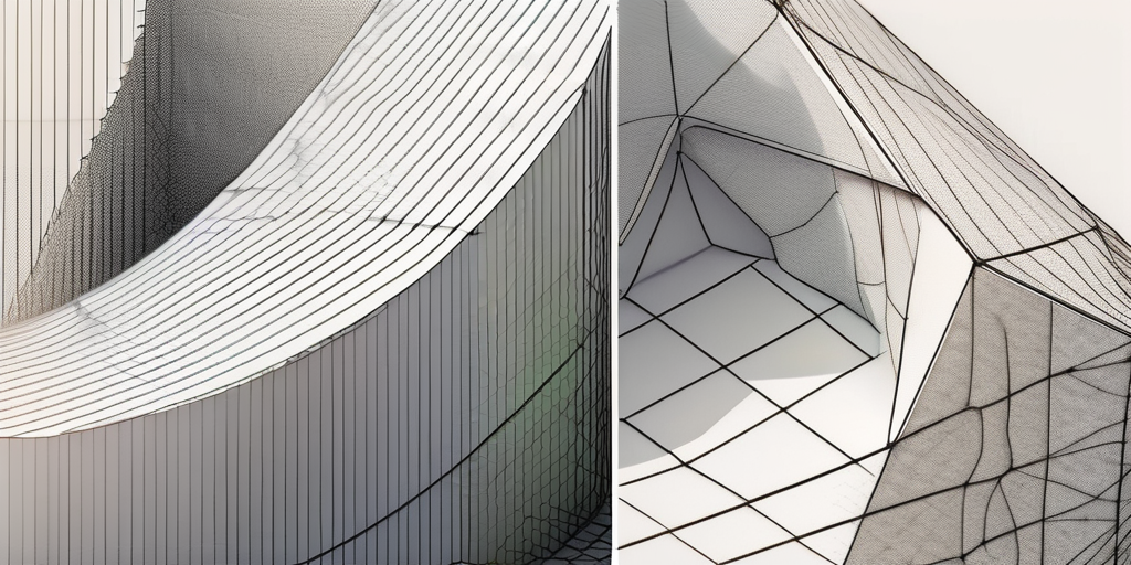
Before diving into the specific techniques, it's important to understand some key concepts in meshing. These include cell types, grid connectivity, cell size distribution, and mesh quality metrics. Cell types can be structured (such as structured grids) or unstructured (such as unstructured triangular or tetrahedral meshes), with each type having its own advantages and limitations.
Structured grids consist of cells that are arranged in a regular pattern, such as a rectangular or hexahedral grid. These grids are relatively easy to generate and have good grid connectivity, making them suitable for simple geometries. However, they may not be efficient for complex geometries with irregular boundaries.
On the other hand, unstructured grids do not follow a regular pattern and can conform to complex geometries more easily. They are particularly useful when dealing with intricate shapes, such as aircraft wings or car bodies. However, generating and manipulating unstructured grids can be more challenging and computationally expensive.
Grid connectivity refers to the relationships between the mesh elements, enabling the calculation of fluxes across cell interfaces. In CFD simulations, it is crucial to accurately calculate the flow variables at the boundaries between cells to ensure accurate predictions. Proper grid connectivity ensures that the flow information is properly transferred between neighboring cells, allowing for a seamless representation of the fluid flow.
Cell size distribution determines the spatial resolution of the mesh, allowing for the capture of different length scales present in the flow. In regions where the flow undergoes rapid changes, such as near a shock wave or a boundary layer, smaller cells are needed to accurately resolve the flow features. On the other hand, in regions where the flow is relatively uniform, larger cells can be used to reduce computational costs without sacrificing accuracy.
Mesh quality metrics assess the geometric properties of the mesh, ensuring it is suitable for accurate simulations. These metrics evaluate various aspects of the mesh, such as element shape, skewness, and aspect ratio. A high-quality mesh should have elements that are as close to regular shapes as possible, with minimal distortion or stretching. This helps to minimize numerical errors and ensures that the mesh accurately represents the underlying physical domain.
By understanding these key concepts in meshing, engineers and scientists can make informed decisions when designing and generating meshes for CFD simulations. The choice of cell type, grid connectivity, cell size distribution, and mesh quality metrics can significantly impact the accuracy, efficiency, and reliability of CFD solutions.
Introduction to Finite Volume Meshing
Finite volume meshing is a widely used technique in CFD, particularly for solving problems involving fluid flow. This method discretizes the computational domain into finite volumes or control volumes, which act as control volumes for the calculation of flow variables.
Principles of Finite Volume Meshing
In finite volume meshing, the governing equations are integrated over each control volume, and the fluxes across the cell interfaces are computed. This approach ensures the conservation properties of the underlying physical laws, such as mass, momentum, and energy. The values of flow variables are typically stored at the cell centers, while the fluxes are computed using gradient calculations.
Benefits and Limitations of Finite Volume Meshing
Finite volume meshing offers several advantages. Firstly, it allows for efficient solution methods, such as the popular pressure-based algorithms. Secondly, it is relatively straightforward to generate high-quality structured or unstructured finite volume meshes. However, finite volume meshing may struggle to accurately capture complex geometries or strong gradients, especially in problems involving solid mechanics or multiphysics phenomena.
Introduction to Finite Element Meshing
Finite element meshing is another commonly used technique in CFD, widely applied to problems involving structural analysis and multiphysics simulations. Unlike finite volume meshing, finite element meshing divides the computational domain into finite elements, which can be triangles, quadrilaterals, or tetrahedra.
Principles of Finite Element Meshing
Infinite element meshing, the governing equations are typically formulated in weak form, which involves multiplying the equations by appropriate weight functions and integrating over the whole domain. This approach allows for the calculation of element matrices and vectors, which are then assembled to form the system equations to be solved.
Benefits and Limitations of Finite Element Meshing
Finite element meshing offers several advantages. Firstly, it provides flexibility in handling complex geometries due to its ability to adapt to irregular shapes. Secondly, it allows for accurate capture of local phenomena, such as stress concentrations. However, finite element meshing can be computationally expensive and may require more user expertise to generate high-quality meshes compared to finite volume meshing.
Comparing Finite Volume and Finite Element Meshing
While finite volume and finite element meshing are distinct methods, they share some similarities and differences in their approaches, influencing their performance in various applications.
Similarities and Differences in Approach
A key similarity between the two approaches is their utilization of discrete elements to represent the computational domain. However, finite volume meshing focuses on control volumes and the computation of fluxes, while finite element meshing emphasizes the assembly and solution of element equations.
Finite volume meshing is generally better suited for CFD problems involving fluid flow, where conservation properties are of utmost importance. On the other hand, finite element meshing is more advantageous for problems involving structural analysis or coupled multiphysics simulations, where geometrical adaptability and accurate stress calculations are critical.
Performance Comparison
The performance of these methods may vary depending on the specific problem and the expertise of the user. In general, finite volume meshing often provides faster and more robust solutions for CFD problems, especially for large-scale simulations where finite element meshing becomes too computationally expensive.
Choosing the Right Meshing Method
Deciding on the appropriate meshing method requires careful consideration of several factors related to the problem at hand and user requirements.
Factors to Consider
Some crucial factors to consider include the nature of the problem (e.g., fluid flow, structural analysis), the complexity of the geometry, the desired accuracy and resolution, computational resources available, and the expertise of the user. Analyzing these factors will guide the selection of the most suitable meshing method for a given application.
Making an Informed Decision
Selecting between finite volume and finite element meshing necessitates a comprehensive understanding of their underlying principles, benefits, and limitations. By considering the specifics of the problem and the desired outcomes, engineers and researchers can make informed decisions to ensure accurate and efficient CFD simulations.