UAV Design with CFD
Optimizing UAV Design with Computational Fluid Dynamics (CFD)
Unmanned aerial vehicles (UAVs) are revolutionizing the way we think about transportation, with new applications emerging every day. Whether for military surveillance, environmental monitoring, or package delivery, UAVs must be designed with precision and efficiency. One of the key technologies advancing the UAV industry is computational fluid dynamics (CFD), which provides designers with an effective tool to accelerate the design cycle and improve UAV performance. In this article, we explore the role of CFD in UAV design and how it can help streamline the process from start to finish.

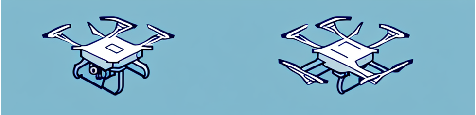
(A selection of UAVs – courtesy Wikipedia)
Understanding the Importance of CFD in UAV Design
Unmanned Aerial Vehicles, or drones, have become increasingly popular in recent years for a wide range of applications, from military reconnaissance to commercial delivery services. However, designing a UAV is a complex process that requires a deep understanding of various fields such as aerodynamics, propulsion, and structure. This is where Computational Fluid Dynamics (CFD) comes in, enabling designers to simulate these systems comprehensively and optimize performance, reducing the need for costly and time-consuming physical testing.
UAV development is a high-risk, high-reward endeavor. A single misstep, especially one leading to a highly public failure, can set off a chain-reaction of negative public sentiment and increased regulatory scrutiny.
CFD involves solving mathematical equations that describe the behavior of fluids, such as air, around an object. The software takes into account the shape of the UAV, the speed at which it is traveling, and the forces acting upon it, among other factors. By simulating the conditions the UAV will encounter, designers can analyze the flow of air around the exterior of an aircraft in great detail.
Perhaps the most visible and widely known drone developer is Amazon PrimeAir.
Amazon’s latest drone platform is a six-propeller, roughly 80-pound carbon-fiber model known as the MK30, touting an increased range and weather tolerance versus the previous MK27-2 platform. The design is shown in the image below, courtesy of Amazon. The drone is capable of cruising speeds of up to 60 knots.

(Amazon MK30 Drone)
Uniquely, the design includes biwings that serve to add during horizontal flight, increasing range, while at the same time serving as propellor guards in vertical takeoff and landing. The six propellors provide a high level of stability during hovering in all weather conditions. With this iteration Amazon’s engineering team has also placed an emphasis on reducing the noise signature of the drone. With the help of STAR-CCM+ CFD software, the team has been able to reduce the sound levels generated by the drone by 25% over previous models with improved propellor design. Wind tunnel testing at the University of Washington has been used to validate and supplement CFD results.

(Amazon’s MK30 Drone in the Wind Tunnel at the University of Washington)
The Role of Computational Fluid Dynamics in UAV Development
CFD is an essential tool in UAV development, as it allows designers to gain insight into how airflow affects various parts of the UAV, such as the wings, fuselage, and propellers. This information can be used to optimize designs, make critical decisions about structural rigidity and build materials, and improve the aircraft's overall efficiency.
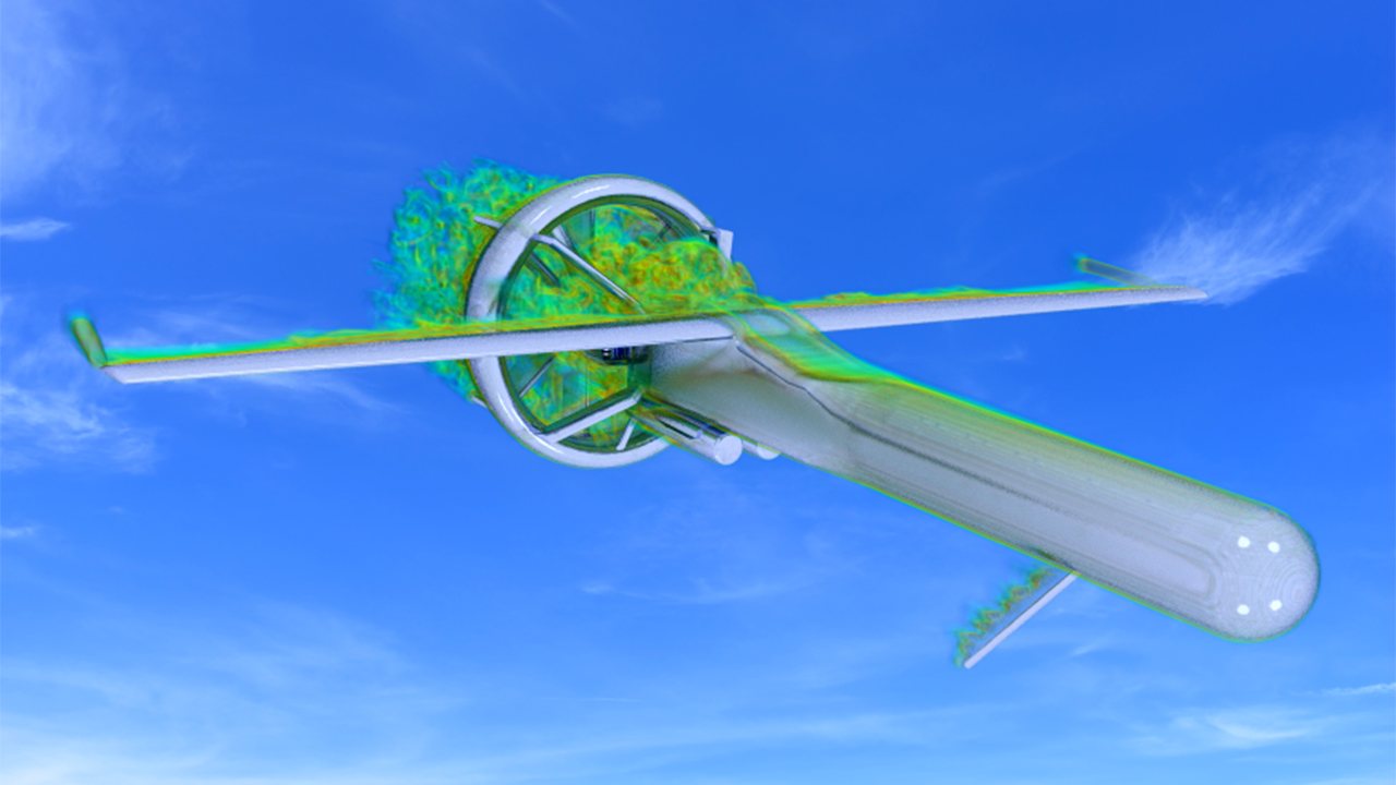
(Computational Fluid Dynamics Simulation of Martin UAV V-BAT Drone – courtesy Siemens Digital Industries Software)
One of the most significant advantages of using CFD in UAV design is the ability to identify possible design issues early in the development cycle, reducing the number of physical prototypes that must be constructed. By analyzing information obtained from CFD simulations, UAV designers can modify and test multiple designs at once, leading to a more optimized design process, and ultimately shorter production times.
Martin UAV, developer of the V-BAT drone, relies heavily on STAR-CCM+ CFD simulations in the design process and has realized substantial reductions in design cycle times for that reason. The V-BAT is a vertical take-off and landing (VTOL) platform utilizing a ducted-fan technology that produces 80% more thrust at equivalent engine powers compared to traditional propellors. The V-BAT is the smallest and most agile drone in its class, with a weight of only 125 lbs and a payload capacity of 25 lbs.

Scale Model of the Martin V-BAT UAV (courtesy Brigham Young University)
According to Zach Hazen, aerodynamics lead at Martin UAV, the integration of CFD into the UAV design cycle allows Martin to “understand our product better, whether the baseline design we have today or a future design. I see high fidelity simulation as a way to stay ahead of the demands we know are coming.”
Benefits of Using CFD for UAV Design Optimization
The benefits of using CFD in UAV design are numerous. Firstly, it allows the designer to optimize UAV performance in terms of range, speed, and stability. By optimizing the airflow around the vehicle, CFD can improve fuel efficiency, resulting in longer flying times and greater mission capabilities.

(CFD optimized cut-off, winglet, and raked wings, courtesy João Carvalho)
By integrating CFD software and an optimization software such has HEEDS it is possible to fully explore large design spaces, analyzing the aerodynamic characteristics of hundreds of UAV designs to minimize drag and noise, while maximizing speed and range. This is particularly important for military UAVs, which need to be able to fly quietly at high speeds to avoid detection and complete their missions successfully. The image below shows the result of an automated optimization sequence for reducing the drag of a UAV at cruise speed (shown in blue), while simultaneously also calculating drag for 4 other environmental conditions. The best weighted design is shown by the asterisk.

(Drag Minimization Across 5 Environmental Conditions, Coupled CFD and Optimization Algorithm)
Key Components of UAV Design and CFD Analysis
UAV design and CFD analysis involve various critical components, such as aerodynamic design, propulsion system integration, and structural analysis. Each of these components is closely linked to the others and requires precise attention to detail to achieve a successful outcome.
Aerodynamics and UAV Performance
One of the most crucial components of UAV design is aerodynamic design. The aerodynamics of the UAV, including lift and drag, impacts the aircraft's speed, stability, and maneuverability. By using CFD to simulate airflow around the aircraft, designers can identify areas of high drag, optimize lift, and reduce turbulence, leading to a more efficient and stable UAV.
Propulsion System Integration
Another application for optimization is in determining the best placement and integration of propulsion systems, thereby reducing weight and reducing the need for excessive structural reinforcement. This not only improves the overall performance of the UAV but also reduces production costs and makes the UAV more affordable for commercial and civilian applications.
The integration of propulsion systems in UAV design is complex, and a precise understanding of the interaction between the propulsion systems on the aircraft and the surrounding airflow is crucial. By using CFD, designers can optimize the placement of propulsion components such as engines, ducts, and propellers, thus reducing weight and improving UAV performance. CFD simulations also make it possible to evaluate and improve the engine's efficiency, enhancing the aircraft's endurance and flight time.

(CFD Visualization of Prop Wash from UAV – visualized by Q-Criterion Indicator of Turbulence)
Structural Analysis and Weight Reduction
Structural analysis is essential to the overall design of UAVs. By analyzing the aircraft's structural strength, designers can make critical decisions about the material and build of the UAV, including fasteners, joints, and support structure. CFD also allows designers to optimize weight distribution, leading to improved stability and overall performance. By integrating CFD into the structural analysis process, UAV designers can reduce weight while preserving strength, ultimately leading to a more efficient, lightweight design.
Streamlining the UAV Design Process with CFD
CFD plays a critical role in streamlining the UAV design process by reducing design cycle time and enabling rapid prototyping. By using CFD simulations to test and iterate multiple concepts and designs, UAV designers can avoid the expensive and time-consuming process of traditional wind tunnel testing. Furthermore, CFD enables greater collaboration among different design teams, enhancing the overall speed and efficiency of the design process.
Rapid Prototyping and Iterative Design
The use of CFD in UAV design aids rapid prototyping in an iterative design processes. By testing designs in a virtual environment, designers can quickly and cheaply identify possible issues and refine their designs in real-time. Iterative design can reduce production time and costs by minimizing the potential for expensive design problems that may not otherwise become apparent until after manufacturing.
NASA recently relied on CFD and rapid prototyping to iterate on design concepts related to its “Greased Lighting” VTOL platform. David North, an aerospace engineer at NASA, explains the process as follows.
"We built 12 prototypes, starting with simple five-pound (2.3 kilograms) foam models and then 25-pound (11.3 kilograms), highly modified fiberglass hobby airplane kits all leading up to the 55-pound (24.9 kilograms), high quality, carbon fiber GL-10 built in our model shop by expert technicians, "
Photos at various stages of iterative rapid prototyping are shown below.

(NASA GL-10 Rapid Prototype Phases)
The program has been a success, with recent flight testing of a 50% scale model recently confirming the simulation results and demonstrating stability and control of the 10-engine remotely piloted aircraft.
Reducing Wind Tunnel Testing Requirements
Wind tunnel testing is a time-consuming and expensive part of traditional aerospace product design. By replacing extensive wind tunnel testing with CFD simulations, UAV designers can significantly reduce the amount of time and money required to complete the design process. Furthermore, CFD enables designers to simulate a much broader range of conditions than is possible with traditional wind tunnel testing, leading to more comprehensive data and better-informed design decisions.
Enhancing Collaboration between Design Teams
CFD can be used as a shared language between design teams. By collaborating across teams and disciplines, UAV designers can ensure that all aspects of the aircraft design are optimized and well-coordinated. CFD enables team members to visualize the overall design, make informed decisions, and work together toward a common goal. By working collaboratively, designers can generate better solutions, reduce errors and improve the UAV's overall performance.
Advanced CFD Techniques for UAV Design
CFD involves complex modeling and simulation technologies, and UAV designers require an in-depth knowledge of these techniques to maximize their benefits fully. In recent years, various advanced CFD techniques have emerged that optimize UAV design, including meshing strategies, turbulence modeling, and high-performance computing.
Meshing Strategies for Complex Geometries
To simulate fluid flow accurately, the CFD software must accurately represent the geometry of the UAV. Meshing strategies are techniques used to break down the aircraft's geometry into smaller, more manageable parts, allowing for an accurate simulation of the airflow. Using advanced meshing techniques, such as adaptive mesh refinement, allows for even greater accuracy and can reduce computational time while improving overall simulation quality.
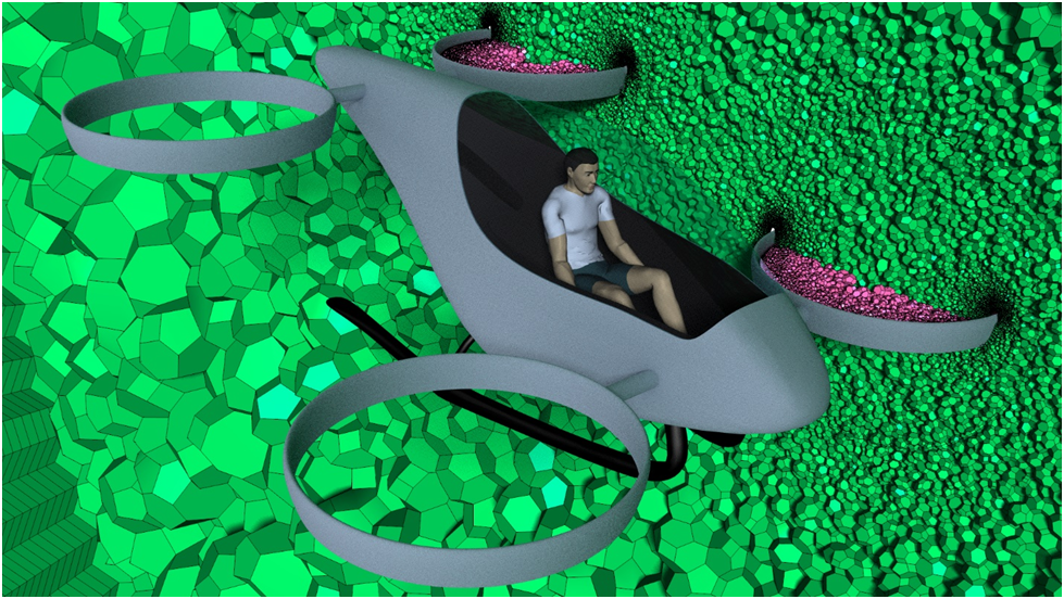
(Example of a Polygonal Mesh for High Fidelity CFD Simulation of VTOL UAV Takeoff and Landing Aerodynamics)
Turbulence Modeling and Simulation
Turbulence in the airflow around a UAV is a complex phenomenon that directly affects the aircraft's stability and performance. CFD simulations enable designers to understand the physics of turbulence and its effects on the UAV design. Through advanced turbulence modeling, designers can simulate different turbulent boundary conditions to optimize the aircraft's aerodynamics and improve overall performance.
What is the k-omega turbulence model?
The K-Omega turbulence model is a two-equation model that solves transport equations for the turbulent kinetic energy and the specific dissipation rate to determine turbulent eddy viscosity terms used in modeling subgrid-scale turbulence via Reynolds’ Stress terms.
The book “Turbulence Modeling for CFD” by D.C. Wilcox is the most comprehensive reference on the K-Omega model, discussing the origin of the model, comparing it to other models, and presenting the latest version of the model. As the originator of the K-Omega model, Wilcox claims the superiority of his model over the K-Epsilon model, and the superiority of the Omega transport equation over other scale equations.
One reported advantage of the K-Omega model over the K-Epsilon model is its improved performance for boundary layers under adverse pressure gradients. Perhaps the most significant advantage, however, is that it may be applied throughout the boundary layer, including the viscous-dominated region, without further modification. Furthermore, the standard K-Omega model can be used in this mode without requiring the computation of wall distance.
The biggest disadvantage of the K-Omega model, in its original form, is that boundary layer computations are sensitive to the values of dissipation rate in the free-stream. This translates into extreme sensitivity to inlet boundary conditions for internal flows, a problem that does not exist for the K-Epsilon models. The problem of sensitivity to free-stream/inlet conditions was addressed by F. R. Menter and the modified Menter K-Omega model is used in STAR-CCM+ in an attempt to address this shortcoming.
The Menter K-Omega turbulence is widely considered one of the leading turbulence models for use in aerodynamics CFD simulations.
High-Performance Computing for Large-Scale Simulations
CFD simulation requires significant computational power to handle the vast number of calculations required to produce accurate results. High-performance computing (HPC) enables designers to run large-scale simulations with greater speed and efficiency, reducing design cycle times and enabling more comprehensive testing. As computing power continues to increase, the capabilities of CFD and UAV design will continue to evolve and provide new opportunities for optimization and innovation.
An example of the importance of HPC in leveraging CFD in the UAV design process is provided by NASA’s experience in designing the V22 Osprey tiltrotor. Although not a UAV by definition, many of the aerodynamic design concepts and challenges are directly translated into UAV platforms. Over the past decade, aerospace engineers and scientists at the NASA Advanced Supercomputing (NAS) facility at Ames Research Center have been able to reduce the error in CFD predictions of rotorcraft hover performance from 2.4% to 0.2%, while simultaneously lowering the computational costs.
Without access to NASA supercomputing capabilities this progress would have been impossible. To resolve flow details in rotorcraft flows, several hundred million to a few billion grid points were needed. A typical CFD simulation required between 1,000 and 6,000 processor cores operating continuously for a few days to a few weeks on the Pleiades and Aitken supercomputers. Each animation often required more than 100 gigabytes of data to be written to disk. These animations proved the most practical way to investigate unidentified features in a flow field such as the turbulent “worms” that surprised many of the researchers and are shown in the image below.

(CFD Produced Visualization of Flow Features in Rotorcraft Simulation – Courtesy Neal Chaderjian at NASA)
Conclusion
CFD technology is revolutionizing the way we think about UAV design, providing a comprehensive and cost-effective tool for optimizing aircraft performance while reducing time to market. By simulating and testing designs in a virtual environment, UAV designers can identify issues early in the design cycle and refine them quickly and efficiently. Advanced CFD techniques such as meshing strategies, turbulence modeling, and high-performance computing offer even greater potential for optimizing the design cycle further.
As the demand for UAVs continues to grow, the importance of CFD in UAV design will only increase, making it an essential skill for any UAV designer or engineer. By using CFD to enhance collaboration, reduce design cycle time, and improve UAV design, we can revolutionize the way we approach transportation, bringing new possibilities to the aerial mobility industry.